


In electrical circuits for current regulationapply resistors. A huge number of different types are produced. To determine the entire variety of details, for each introduced a conventional designation of the resistor. They are marked in various ways, depending on the modification.
A resistor is a device that haselectrical resistance, its main purpose is to limit the current in the electrical circuit. The industry produces various types of resistors for various technical devices. Their classification is carried out in different ways, one of them is the nature of the change in resistance. According to this classification, there are 3 types of resistors:
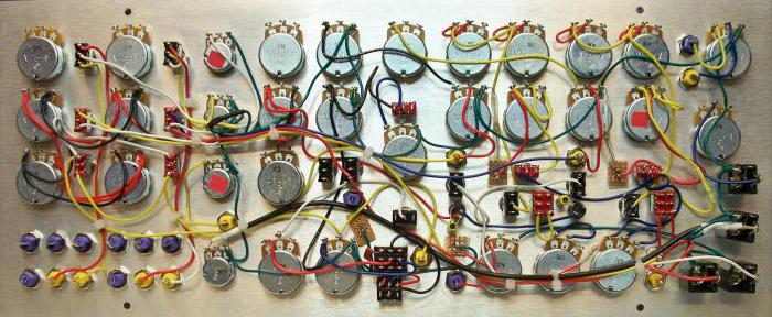
Some types of resistors examined are shown in the photo below.

There are 3 main types of electronic mountingcomponents: mounted, printed and micromodules. Each type of installation has its own elements, they vary greatly in size and design. Resistors, capacitors and semiconductors are used for surface mounting. They come with wire leads so that you can solder them into the circuit. Due to the miniaturization of electronic devices, this method gradually loses its relevance.

For print and micromodular mounting oftensmd resistors are used. They are very small in size, easily integrated into the PCB and micromodules by automata. They are available in various nominal resistances, capacities and sizes. The latest electronic devices mainly use smd resistors.
Nominal resistance, expressed in ohms,kilohms or megohms, is the main characteristic of the resistor. This value is given in schematic diagrams, applied directly to the resistor in alphanumeric code. Recently, the color designation of resistors has often been used.
The second most important characteristic of a resistor ispower dissipation, it is expressed in watts. When a current passes through it, any resistor heats up, that is, it dissipates power. If this power exceeds the permissible value, the destruction of the resistor occurs. According to the standard, the designation of the power of resistors on the circuit is almost always present, this value is often applied to its case.
Of great importance is the error, ordeviation from the nominal value, measured in percent. It is impossible to exactly make a resistor with the stated resistance value, there will definitely be a deviation from the specified value. The error is indicated directly on the body, usually in the form of a code of color bars. It is estimated as a percentage of the nominal value of resistance.
Where there are large fluctuationstemperature, the dependence of resistance on temperature, or the temperature coefficient of resistance, is abbreviated, short designation - TKS, measured in relative units ppm / ° C. TKS shows which part of the nominal the resistance of the resistor changes if the temperature of the medium increases (decreases) by 1 ° C.
When drawing diagrams required compliancestate standard GOST 2.728-74 on conventional graphic symbols (UGO). The designation of a resistor of any type is a rectangle 10x4 mm. On its basis, graphic images are created for other types of resistors. In addition to the HSD, the designation of the power of the resistors on the circuit is required, this facilitates its analysis during troubleshooting. The table below shows the UGO constant resistances with the indication of the dissipated power.

The photo below shows the fixed resistors of different power.

UGO of variable resistors are applied to the circuit diagram in the same way as fixed resistors according to the state standard GOST 2.728-74. The table shows the image of these resistors.

The photo below shows the variable and trimming resistors.

International standards denoteThe nominal resistance of the resistor on the circuit and on the resistor itself is slightly different. The rules of this designation, along with examples of examples are given in the table.
| Full designation | Abbreviation | ||||||
| unit of measurement | Identified units rev. | Limit nominal resistance | on the diagram | on the body | Limit nominal resistance | ||
| Ohm | Ohm | 999,9 | 0,51 | E51 or R51 | 99,9 | ||
| 5,1 | 5E1; 5R1 | ||||||
| 51 | 51E | ||||||
| 510 | 510E; K51 | ||||||
| Kiloi | kOhm | 999,9 | 5.1k | 5K1 | 99,9 | ||
| 51k | 51K | ||||||
| 510k | 510K; M51 | ||||||
| Mega | MOhm | 999,9 | 5.1M | 5M1 | 99,9 | ||
| 51M | 51M | ||||||
| 510M | 510M | ||||||
Из таблицы видно, что обозначение на схемах Resistors of constant resistance are made alphanumeric code, first comes the numerical value of the resistance, then the unit is indicated. On the body of the resistor is taken in numerical designation instead of a comma to use the letter, if it is ohms, then put E or R, if the kilomas, then the letter K. In the designation of megohms instead of a comma the letter M is used.
The color designation of the resistors was taken,that it was simpler to put information on technical characteristics on their case. To do this, apply several color strips of different colors. In total, 12 different colors are taken in the designation of the strips. Each of them has its own specific meaning. The color code of the resistor is applied from the edge, with low accuracy (20%), 3 strips are applied. If the accuracy is higher, you can already see 4 bars on the resistance.

With high precision resistor is applied 5-6strips. For a label containing 3-4 strips, the first two indicate the resistance value, the third strip is a multiplier, this value is multiplied by it. The next bar determines the accuracy of the resistor. When marking contains 5-6 strips, the first 3 correspond to resistance. The next bar is a multiplier, the 5th bar is accurate, and the 6th one is temperature coefficient.

To decipher the color codes of resistors there are reference tables.
Surface mounting is when all parts arelocated on the board from the printed tracks. In this case, the holes for mounting elements are not drilled, they are soldered to the tracks. For this installation, the industry produces a wide range of smd components: resistors, diodes, capacitors, semiconductors. These elements are much smaller in size and technologically adapted for automated installation. Using smd-components can significantly reduce the size of electronic products. Surface mounting in electronics has almost supplanted all other types.

With all the advantages of this installation, it has several disadvantages.
The first smd resistors are differentstandard sizes. The smallest size is 0402, a little more is 0603. The most common size of the smd resistor is 0805, and the larger one is 1008, the next size is 1206 and the largest is 1812. The smallest sizes have the smallest power.
The designation of smd-resistors isspecial digital code. If the resistor has a size of 0402, that is the smallest one, then it is not labeled in any way. Resistors of other sizes additionally differ in the tolerance of the nominal resistance: 2, 5, 10%. All of these resistors are marked with 3 digits. The first and second of them show the mantissa, the third - the multiplying factor. For example, code 473 is read as R = 47 103 Ohm = 47 kΩ
All resistors that have a 1% tolerance, andframe sizes greater than 0805, are marked with four digits. As in the previous case, the first digits indicate the nominal mantissa, and the last digit indicates the multiplier. For example, the code 1501 is deciphered as: R = 150 101= 1500 Ohm = 1.5 kΩ. Other codes are read in the same way.
Correct designation on resistor circuits andother elements - the main requirement of state standards in the design of electronic and electrical products. The standard sets the rules for the symbols of resistors, capacitors, inductances and other components of the circuits. The diagram indicates not only the designation of a resistor or other circuit element, but also its nominal resistance and power, and for capacitors, the operating voltage. Below is an example of the simplest schematic diagram with elements designated by the standard.

Knowledge of all conventional graphics andreading alphanumeric codes to the elements of the schemes will allow you to easily understand the principle of operation of the scheme. In this article only resistors are considered, and there are quite a lot of circuit elements.


